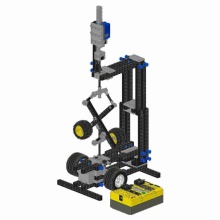

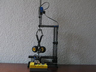
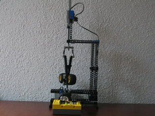
In order to show the students what a Hopf bifurcation is, I designed a model of a Watt Governor using only ordinary LEGO bricks as well as the LEGO Mindstorms Robotic set. Below, you see two video's. The first video has been made with a parameter setting for which the equilibrium is unstable and for which a stable limit cycle exists (the flyball arms go up and down). The second video has been made with a parameter setting for which the equilibrium is stable. The only difference between the two cases is the value of the gain in the feed-back loop.
Description of the Watt governor
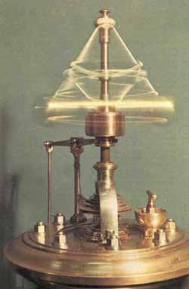
James Watt used the so-called "flyball governor" to regulate the speed of his steam engines (1787). In the picture on the right you see such a flyball governor. It consists of two flyballs which are connected to the pindle by two flyball arms. The spindle of the governor is directly connected to the shaft of the steam engine. The flyballs move upward when the spindle speed increases due to the centrifugal forces. The flyball arms are connected to a throttle valve that regulates the steam input to the engine. If the spindle speed increases, then the flyballs arms move upward thereby closing the throttle valve, which reduces the steam input and the engine is therefore slowed down. The flyball governor therefore regulates the speed of the steam engine. It is in fact one of the first feed-backward mechanisms. The amount of feed-backward, i.e. the "gain", is determined by the kinematics between the flyball arms and the throttle valve. The stationary movement of the combined engine-governor system is an equilibrium of the system. If everything goes well, then this equilibrium is asymptotically stable, i.e. a disturbance in the load of the engine will die out and the system returns to stationary movement with a constant desired engine speed. However, if the gain is taken too large (if the flyballs influence the throttle valve too much), then the equilibrium becomes unstable and a stable limit cycle is created. This is what we call a Hopf bifurcation. The speed of the engine as well as the height of the flyballs will therefore not be constant for a large gain but will oscillate (which is undesirable).
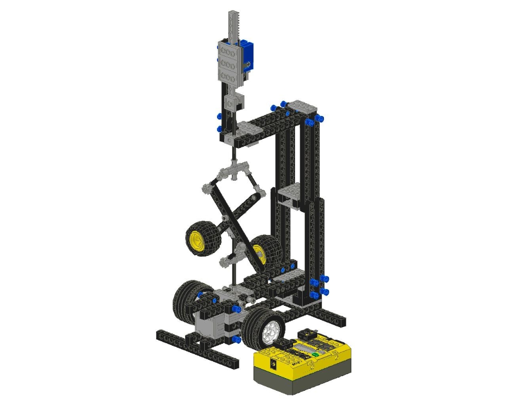
- The LEGO Watt Governor
-
The flyball governor is made using LEGO TECHNIC bricks. The spindle is driven by an 9V LEGO electromotor. The height of the flyballs is measured using a rotation sensor which is connected to the RCX, being a LEGO programmable brick. On the RCX runs a computer program that determines the voltage to the electromotor. If the flyballs rise, then the electrical power to the electromotor is reduced by the RCX. The RCX together with the electromotor therefore represents the steam engine and throttle valve. In the next sections you will find the building instructions and part lists as well as the computer program for the RCX. The computer program has been written in NQC, a programming language specially designed for the RCX.
- Building Instructions
-
You can download the building instructions (a step-by-step guide) here
- Computer Code
-
The following program for the RCX is written in NQC. The program reads in the angle of the rotation sensor and stores it in the variable ANGLE. Subsequently, the motor power M is determined by the difference of a constant ANGLEBAR and ANGLE. The gain is KU/KL. The program has to use two constant (KU and KL) to specify the gain, because the RCX processor can only calculate with integers. Find two parameter settings for the gain KU/KL such that the Watt Governor has a stable equilibrium for one setting and a limit cycle (oscillatory motion) for another setting and store these programs in two slots of the RCX.
Contact

Remco I. Leine
Prof. Dr. ir. habil.Direktor